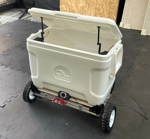
Autonomous Cooler Project
Link to demo video: https://youtu.be/l7qm9mDklhA
There are two main modes of operation for our cooler: manual and autonomous control. In manual mode, a user can direct the robot through simple arrow keys to command the cooler forward, backward, left, and right. Furthermore, manual mode also offers the ability to open or close the lid of the cooler via a toggle button on our graphical user interface (GUI). Finally, a thermistor displays the temperature reading to the user, allowing one to see when the cooler needs to be refilled with ice.
The autonomous mode of our project takes this core functionality of the cooler to the next level. In this mode, the cooler utilizes a webcam and a computer vision algorithm to track a particular color, sending differential velocities to the drive motors to keep the desired color centered. This algorithm is then coupled with an ultrasonic sensor, ensuring that the cooler is able to stop once reaching within a certain distance to an object. In addition to autonomous locomotion, this mode provides the ability to open and close the lid through voice commands spoken into a laptop.

Figure 1. Color detection algorithm used for finding the centroid of the largest yellow object in the frame, shown in three different positions
In developing the hardware for our semi-autonomous cooler, we aimed to build a product that is practical to use while focusing on bolstering the software features implemented in our project. To achieve this, we designed our robot around a robust aluminum frame capable of supporting the cooler while concealing and protecting our electronics within. The cooler is driven by two 12V DC motors mounted to semi-rigid rubber wheels which provide traction on any terrain. Additionally, an off-road caster at the back of the robot maintains stability and allows for easy turning. In addition to the DC motors, servo motors were also selected to operate the lifting and closing of the cooler’s lid. Finally, we utilized two different microcontrollers for this project to support various functions: a Cypress PSOC 6 to handle the real time component, and a Raspberry Pi to perform the computer vision tasks.

Figure 2. CAD assembly and parts designed for cooler's drivetrain (motor mount and hub adaptor)
This project not only gave me additional experience in mechanical design and mechatronics, but also taught me how to utilize LabVIEW to capture data and control machine activities. Our ambitions for incorporating both manual and autonomous modes and integrating so many different features proved to be a challenge, but through this process I developed a more profound and applied understanding of embedded systems and microprocessor architecture.


